|
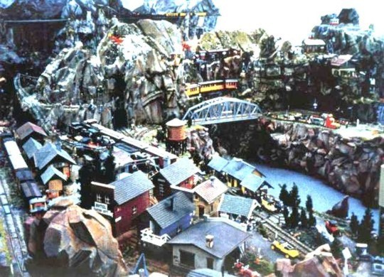
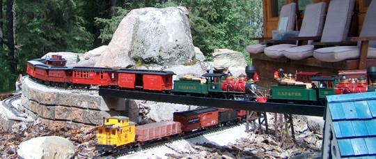
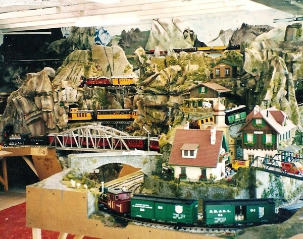
Click Logos to see photos of my outdoor and indoor model railways
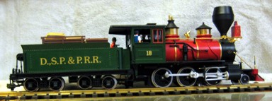
Today, G scale continues to increase in popularity and sophistication. Many like its size, which is "big enough to get one's hands on" while still being able to turn in a 4 foot diameter. The trains are weather proof (some are kid-proof too), and the track can be left outdoors all year round. When used in a garden setting, the combination of soil, plants, rock, and changing sunlight together with such options as smoke puffing engines and a system recreating steam or diesel sounds, bells, whistles and horns, combine to make the G scale experience one of incredible realism and satisfaction. A layout indoors is also a great source of relaxation for the whole family. Of course, a train running around the tree at Christmas time brings back fond memories for many.
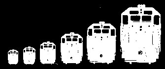
Large Scale model railroading is also very popular. It is the fastest growing facet of our hobby, and in time and money spent, exceeds most of the better known smaller scales, with the exception of HO and possibly N scales. Large Scale models are also given the generic name of "G Scale", even though this is technically not correct. The scale ratios for large scales range from 1:13 to 1:32. The most common are 1:20.3, 1:22.6, 1:29, and 1:32 - see table on Page 2 for more details. Large Scale, as the name suggests, is big - locomotives and rolling stock are roughly twice as long and therefore 8 times more volume and weight than O scale. Compared to HO, Large Scale equipment is 4 times longer and 64 times the volume and weight. That's pretty big! A typical loco is 25 to 30 inches long and weighs 5 to 10 pounds – some weigh in at 50 pounds. Large Scale starter sets and individual components are available from several major manufacturers and from many hobby shops. Some hobby shops cater exclusively to large scale modelers. These sets are usually rugged enough to be set up outdoors (garden railroading) or indoors (model railroading). Many people start with a small set around the Christmas tree or a small setup on the grass in the summer. If the family is keen to expand, the train set can be augmented and, if outdoors, a rock garden or other scenic effects can be added. Large scale model railways or garden railways can be built to precise scale, if desired, to represent a particular railway. Many are semi-scale and represent more generic railway activities. Others are purely whimsical with nothing but fun or fantasy in mind. My personal style of modeling is to create the illusion of realism, not “real” realism, even though scale, track gauge, and space limitations force me to make many compromises. Anyway, it’s your railway and you can run it any way you want! Price is somewhat proportional to quality, longevity, fidelity to detail, and intended market (children vs adults, collectors vs modelers). A good quality starter set will run between CDN$ 200 and CDN$400 (US$175 to US$350). Use your common sense when judging price vs quality - think about who makes it, where are you buying it, where can it be serviced. Don’t be over-eager about a deep discount from “retail” prices. The so-called “retail” price is the Manufacturer’s Suggested Retail Price (MSRP). Any shop that sells at full MSRP probably doesn’t sell very much or expects you to deal (haggle) over price. Most hobby shops and mail order discount stores routinely sell at 20 to 40% less than MSRP - this is the normal “street price” for these trains. Watch for close-outs on the web sites - these may offer 50 to 70% off MSRP! Be sure to shop around. Good luck with your large scale empire, and above all, have fun!
Large Scale and garden railroaders mostly use 45 mm gauge track, usually called Gauge 1 or #1 Gauge, and sometimes (incorrectly) called G Gauge track. Gauge 1 represents different gauges in each of the popular modeling scales, as listed in the table below (based on proposed NMRA standards):
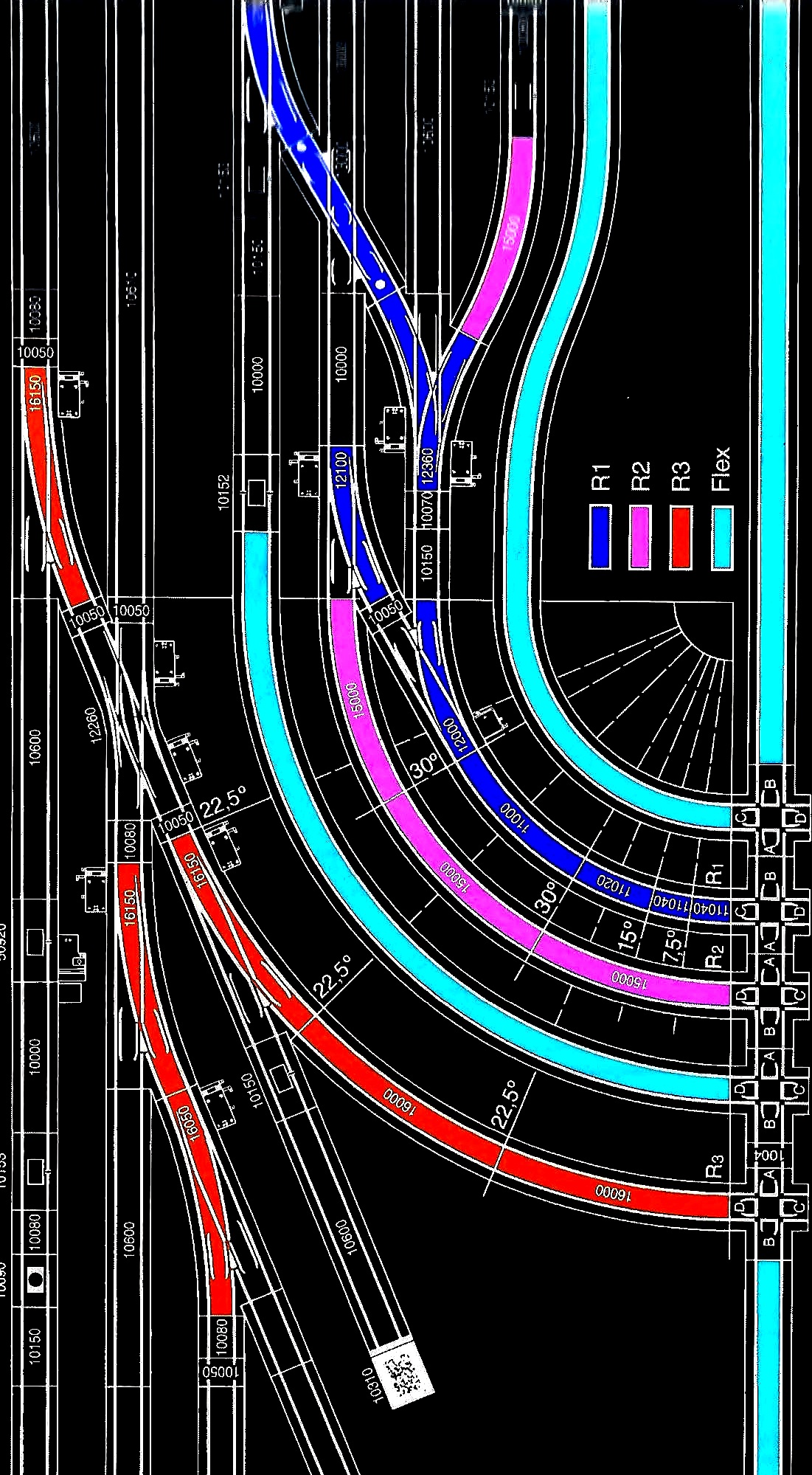
If you love to watch trains run, then scale, gauge, and realism won't matter much. If you want realism, some compromise, such as track gauge, is probably acceptable. For real accuracy, you will also have to do a bit of research to verify that the car style, paint job, and dimensions are a reasonable representation of the era, locale, and road you are modeling. Or you might do a bit of kit bashing, detailing, or repainting to achieve your goal. Want more?? Click here: Scale and Gauge Encyclopedia. Track for use with Large Scale models is manufactured by a number of suppliers. It is normally "Gauge 1" or 45 millimeter gauge, made of brass or stainless steel on UV resistant plastic ties. Sectional track as well as flex-track is available. Using track sections is fast and easy but curve diameter is limited to a few fixed dimensions -- usually 4, 5, and 7 feet (often called R1, R2, and R3) ). Wider diameters of 8, 10, and 20 feet may be available in limited supply. Flex-track can be shaped to any reasonable curve diameter, but this is considerably more work than connecting sectional track. Hand laid rails on wooden ties is also managed by a few very patient modelers. The geometry of sectional track needs a bit of explanation. Recall that a full circle is 360 degrees (once around a clock face is 360 degrees). Curved sections of track are sold with 12 sections per full circle for the 4 foot diameter, making each section a 30 degree arc of the 360 degree circle. The larger diameter sections come with 16 sections to a circle, giving 22.5 degree arcs of that 360 degree circle. To make a model railway, that completes a circuit in your backyard, you need at least enough sections to make up 360 degrees. If your track plan has reverse curves, you will need more sections to get the loop to close -- 1 extra for each reverse section. You can mix and match different diameters as long as the net result is 360 degrees of arc. There are 1, 2, and 4 foot straight track sections, left and right hand turnouts (switches), and 30 and 90 degree crossings to extend your layout beyond the basic circle. The diagram below suggests some of the possibilities (based on LGB track part numbers). Notice that some "odd" sized track sections may be needed to make up the connections between major components. These keep the "geometry" from getting skewed. Note that all sectional track is made to metric standards -- a "1 foot" section is actually 300 millimeters long (about 1/5 inch short of a "real" foot).
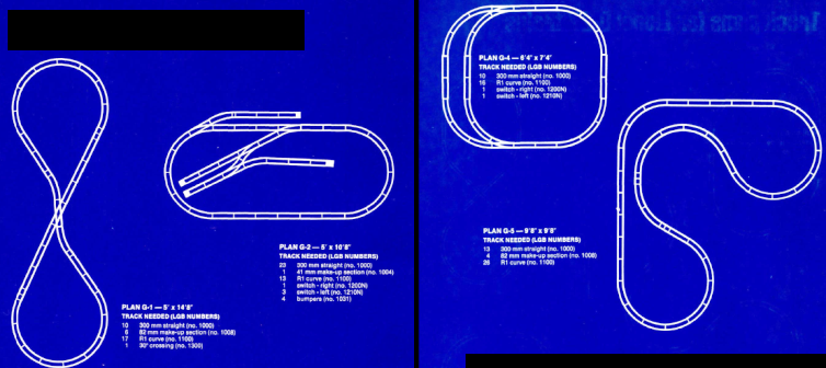
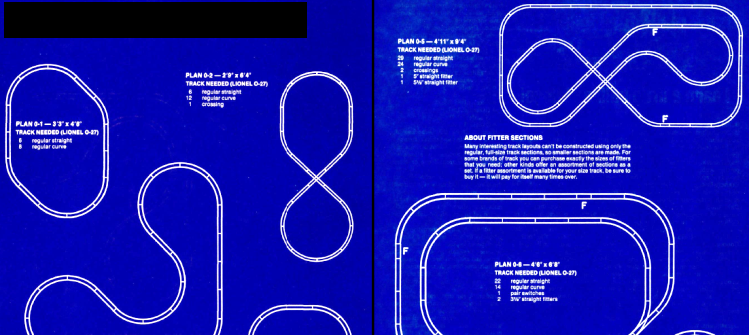
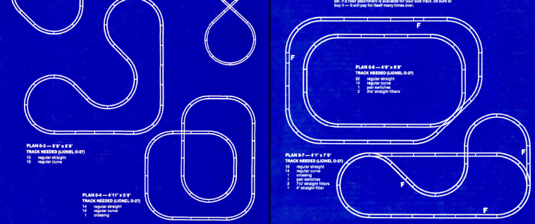
Planning an indoor or outdoor large scale railway is determined by balancing several factors: available space, terrain,, and cost are limiting factors, simplicity versus complexity of operation are personal choices as are fidelity to realism or just plain fun. Below are some track layouts designed mostly for continuous operation, whiles one include limited switching possibilities.
To do justice to the industry, some models are made to one of the specific scales and are very faithful reproductions of a specific car or engine. These are often dubbed fine scale models even if track gauge and wheel dimensions are a little off. However, there is nothing to stop you from using a beautiful 1:20.3 finescale narrow gauge Mogul locomotive as a 1:32 scale standard gauge locomotive. It will still look gorgeous! Here are some typical model dimensions:
Many Large Scale freight cars and locomotives are very generic and are painted for many different railways, even if that railway never used that kind of locomotive or railcar. Some models have been reshaped by shortening (so they will go around the sharper curves) or by changing proportions for more pleasing eye-appeal. Some models represent equipment that never existed anywhere. Choose your rolling stock carefully to please your own eye and you will be a happy railroader.
USA Trains paints the same mold of old-time freight cars for standard gauge A or #1 scale, 3 foot narrow gauge F, G, or H scales, and 2 foot narrow gauge M scale. They also make 1:29 scale diesels and modern era freight cars that could not be considered for F, G, or H scale narrow gauge, unless your sense of whimsy allows this sort of mix and match in the same train. Bachmann offers steam era freight and passenger equipment lettered for both standard gauge and narrow gauge roads. The same rules apply - the models are #1 or A scale when painted for standard gauge and F, G, or H scale when painted for narrow gauge roads. Bachmann also makes a line of F (1:20.3) scale locomotives and freight cars with high quality detail correct for 3 foot gauge on 45 mm track.
Piko has entered the G Scale market to compete directly with Marklin/LGB. Pola, Piko, Aristocraft, Bachmann, and a few others make railway structures, commercial buildings, and houses. By watching ads in the modeling magazines (Garden Railroading or Finescale Railroader), you will find a number of plastic or wooden structures, bridges and accessories suitable for indoor or outdoor railways. All of the above offer people and animals, as well as Preiser, Schneiders, Just Plain Folk, Elita Modelle, Jones, and Noch. Watch the dollar stores for great bargains in “no-name” brand figures. Vehicles are also needed to add realism. Ertl, Liberty, SpecCast, and Revell offer lower priced models at 1:16 to 1:34 scale. A few of these models are advertised as 1:25 scale when in fact they are 1:34 or smaller – watch the driver’s cab – if you can’t visualize a scale person sitting there, the model is probably too small. More expensive models in 1:18, 1:24, and 1:32 scales can be had from Franklin or Danbury Mint.
1.
Magazines, Books, and Videos
4.
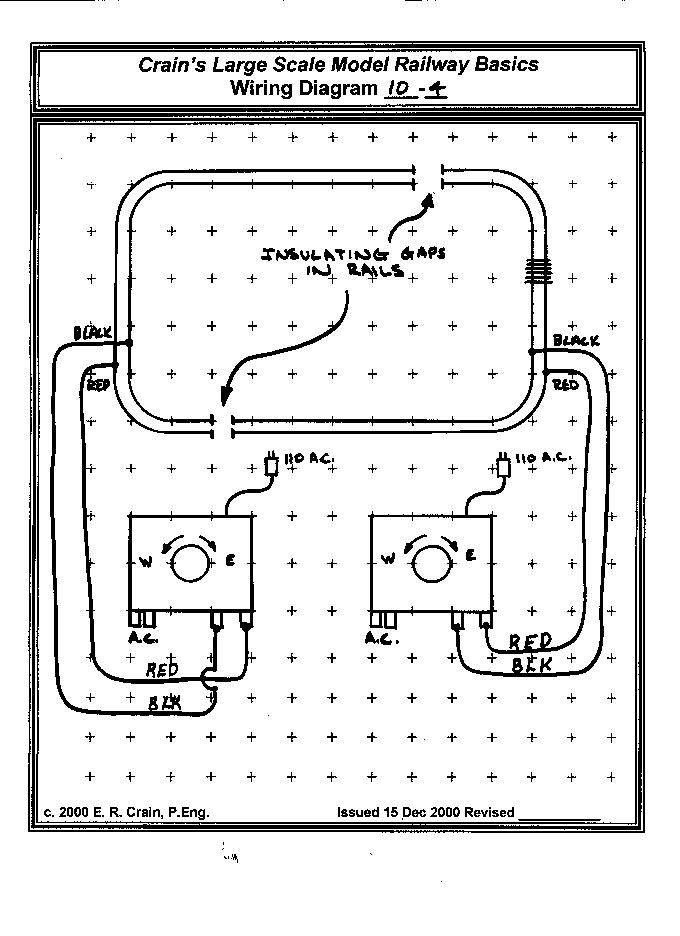
Internet Portals, Classifieds, Discussion, Links An analog power supply contains electronic circuits that convert household AC power to the lower voltage DC required by the trains. Train speed is controlled by a knob or slider that is moved to adjust the voltage applied to the rails. Train direction is controlled by a switch that reverses the polarity of the DC to the rails. There may be other features, such as momentum effects, amp and/or voltmeters, or indicator lamps. Read the owners manual to learn how to use these features. You need well filtered DC from your power supply. Large scale engines do not need pulsed power or ripple DC, which can seriously damage motors and sound systems. In contrast to analog power supplies, Digital Command Control (DCC) uses a fixed voltage (analog) power supply and sends digital commands to decoders in each locomotive to control speed and direction. Each power supply will have a built-in circuit breaker. Some reset automatically after being tripped, others require a manual reset. If the circuit breaker trips, you have some bad track wiring, a derailed train, faulty wiring inside a locomotive or car, or some water where it should not be. Be sure to solve the problem before you reset the circuit breaker. Wires between your power supply and your track should be heavy gauge (22 gauge minimum, 18 gauge is better) and firmly attached to the rails by screws or solder. Run additional wires and connect to the track every 20 feet or so. Outdoor wiring must be weatherproof and protected from damage by feet and lawnmowers. Most power supplies also have low voltage (12 to 18 volts) AC terminals to run lights and other accessories. Do not connect these terminals to the track - you will burn out the motors in the engines. Do not connect the AC terminals of one power supply to the AC of any other power supply - you could get 110 volts across the accessory instead of 18 - SNAP - CRACKLE - POP - WOW!!! ALWAYS turn off or pull the plug on a power supply before connecting wires.
Approximate
amperage draws from large scale "things"
Example 1: Double headed Moguls, short train, sound, smoke, headlights, level track Amps = 2 x (0.5 + 0.2 + 0.1 + 0.1) = 1.8. A starter set power supply won't even budge this train - the circuit breaker pops immediately. A low cost 2 amp power pack will do but might run hot. A 5 amp supply is safer.
Example 2: A-B-A Diesel, 2 motors and 3 lights in A units, sound in B unit, 4 smoke units, 5 passenger cars with 4 bulbs each Amps = 2 x 0.8 + 2 x 3 x 0.05 + 0.2 + 4 x 0.1 + 5 x 4 x 0.05 = 3.5. A 5 amp power supply will do fine, but you couldn't run a second large train on the same system. The best power supplies are rated at 10 or 15 amps, but will usually only deliver 8 or 12 amps, even on a short circuit. Some supplies are rated by their VA (Volt - Amp) or their wattage capacity. The amp rating is found by dividing the VA or watts rating by the maximum output voltage. For example, a power supply with a 70 VA rating is equivalent to 70/18 or roughly 3.5 amps. NOTE: a 70 VA power supply will NOT supply 7 amps at 10 volts or 14 amps at 5 volts - the rating is its MAXIMUM, and at 10 volts it will probably put out even less amps than it will at 18 volts. They are purposely designed this way to prevent them from being used as arc welders! Most large scale locomotives run at rational speeds with 10 to 12 volts on the rails on level track. Engines with a heavy train may stall on grades unless track voltage is raised a bit - 14 to 16 volts might be needed. Trains with lots of lights, multiple locomotives, or DCC decoders will also need a little more voltage. Because of internal losses and aging, you should deduct 10 to 20% from any published rating to determine if you have a big enough power supply. Components inside power supplies can burn out or change value with age, placing high voltage spikes on the track. This can burn out sound systems and even locomotive motors. Pull the plug and get the power supply serviced if there are any problems!
Some
newer large scale power supplies put out 24 to 30 volts. Cheaper
locomotives (some have motors rated at 12 volts max) may not survive
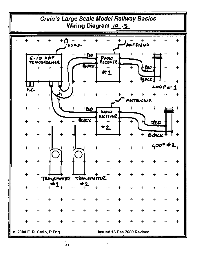
these high voltages. Here, the power supply has provision for a handheld speed and direction control module with a connecting cable to the power supply. This allows you to get closer to your train, which is handy when switching cars or testing track. 2. Analog power supply with un-tethered walk-around control. This system has a handheld transmitter that sends radio or infra-red signals to a receiver connected between a normal power supply and the track. The range is up to 300 feet and no cable is involved. Some handhelds allow you to control two or more different receivers, each running a different train on a different piece of track. Each track section must be electrically isolated from all others. 3. Onboard battery power with un-tethered walk-around control. The power supply is a battery pack in the tender or a trailing car that is controlled by a hand held transmitter. The receiver is in the train, connected between the battery pack and the locomotive. No power is needed on the tracks but some re-wiring of the locomotive is required. Radio controlled model car components can be used. It is illegal and dangerous to use model aircraft R/C systems in trains or cars. 4. Onboard radio receiver and un-tethered walk-around control. Here, the radio receiver is in the train, as in battery operation, but the power comes from the track. Dirty track can cause loss of control (glitches). 5. Digital command control (DCC) with tethered walk-around control. Instead of an analog radio receiver in the locomotive, there is a digital decoder. It receives digital signals from the tracks that are sent by the handheld controller. The controller is plugged into a socket that is connected to the tracks. However, the train continues with its last command when the controller is unplugged, so you can move along with the train to the next socket. Decoders must be installed in all locomotives. 6. Digital command control (DCC) with un-tethered walk-around control. Instead of sockets, a radio receiver is connected to the track to receive the digital signals from the handheld radio transmitter. 7. Digital command control (DCC) with computer control. A computer program sends the commands to the locomotive decoders. This requires trackside detectors so that the program knows where the trains are. The operator can also control several trains from the keyboard. You will need expert advice for this. 8. Live Steam Power. Want a real challenge? Try live steam with or without radio control. It’s fussy but fun for those with the knack for it. Low cost beginner locos (Accucraft, Mamod and Brandbright) are available as well as expensive, fine scale models (Accucraft, Aster, and others).
You
might consider the walk around radio controllers, mentioned above,
to run the separate tracks. One large power supply with 3 or 4
radio-receiver speed controllers is a reasonably inexpensive and
flexible system. One or two handheld transmitters will be needed
(eg AristoCraft Train Engineer system, now labeled Crest Train
Engineer Several battery powered, radio controlled trains can be run on the same track – that’s the appeal of battery power with R/C. One or more additional trains could also be run under track power. Digital command control (DCC) also allows multiple trains on one track. Locos require some re-wiring for battery or DCC operation. DCC for large scale is available from LGB, Locolinc, and others. Battery Backshop and Reedís Hobbies offer radio control and batteries specially designed for large scale trains. For battery operation, be sure to disconnect all sources of track power to the locomotive; otherwise, the battery will end up powering other trains through the track. For automatic control of multiple trains, read on!
When
your track layout comprises two or more independent ovals, control
of each is simple and requires no special electronic circuitry.
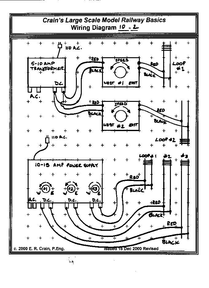
Connect one power supply with built-in speed controller to each
loop. I recommend strongly that you use colour coded wire between
the controller and the track. I use red and black hook-up wire
from Radio Shack. LGB offers red and blue wire (LGB 51230). Connect
the red wire to the outside rail on each loop and the black (or
blue) wire to the inside rail. Keep the colour code and inside
vs outside colour constant for all your wiring. ALWAYS turn off
or pull the plug on a power supply before connecting wires.
Connect
the wires to each rail securely. LGB sells a pair of thumbscrew
terminals for this purpose (LGB 50160 or 50161). You can also
solder the wires to each rail. Run separate wires to the rails
every 20 feet or so. Mark your direction control switch with labels
that indicate train direction, eg. CW = clockwise, CCW = counterclockwise,
or East and West. I equate Eastbound with Clockwise.
Alternatively,
you can use a single power supply with multiple speed controllers,
either built into one control box (Bridgewerks) or
as separate pieces (LGB).
A
better approach is to use one good power supply with separate
radio controlled speed controllers connected to each independent
loop (AristoCraft Train Engineer system).
Here,
we are trying to run two or more trains on the same track, with
enough manual control to prevent collisions.
The switch turns off the power to a portion of the track, thus stopping the train until the switch is moved back to the “run” position. You can use an “on/off” toggle switch from Radio Shack, or one of the switches on an LGB 51800 switch box. Commercial toggle switches should be automotive quality, designed for 12 volt DC high current applications. They are also known as “flip” switches. A version of this circuit using LGB relays activated by the trains is described on Page 19.
View full size Wiring
Diagram 10-5. All this is done with relays. Don’t panic – it’s easy!! The next few pages will describe several automatic circuits that work well on my railway. They use LGB’s EPL switching components with LGB’s 50101 Jumbo power supply. The Jumbo has no AC terminals, so you also need an AC transformer like LGB’s 50111. You can use other power supplies with the EPL relays, but there will be no momentum effects. The LGB Jumbo is the only power supply with built-in momentum and timer features that can be controlled by trains passing over train sensors. Without momentum, trains start and stop with a jolt. You will need basic hand tools such as small screwdrivers and wire cutters, hookup wire, and (rarely) a soldering iron, solder, and electrical tape. There are six essential components from the LGB EPL system: 1. LGB 12010 Switch Motor - these switch turnouts and/or electrical connections. 2. LGB 17100 Train Sensor - these trigger the LGB 50101 timers or an LGB 12010 switch motor when a locomotive with a 17010 magnet passes over it. LGB calls them Track Contacts, but they do not contact the track, so I have chosen a more meaningful name. They are, in fact, magnetic reed switches. 3. LGB 12070 or 12030 Auxilliary Switch - these switch electrical power from one place to another, and plug into the LGB 12010 switch motor. 4. LGB 17010 switching magnet - these are glued to the underside of each locomotive to trigger the LGB 17100 train sensor. 5. LGB 51750 momentary contact control box. 6. LGB 51800 on/off control box. The latter two control boxes have switches for four circuits and are weatherproof.
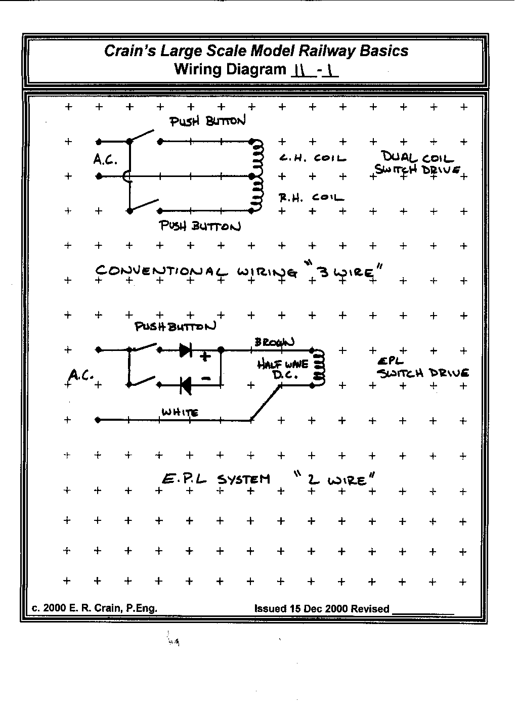
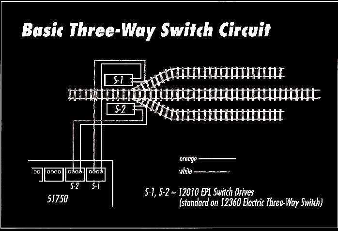
Both
the LGB 17100 Train Sensor and the LGB 51750 Control Box contain
diodes that allow a two wire connection to switch drive motors,
instead of the more traditional three wire system. This saves
a lot of wire on a large scale railway. The diodes pass “half-wave
DC” to the switch motor. Positive DC throws the drive in
one direction; negative DC throws it the other way. Conventional
switch drives have two coils wound in opposite directions to accomplish
this. Wiring errors can burn out the diodes instantly, so follow
the instructions on the following pages carefully.
Use
a colour coded wire that is different than your track wiring.
I use Radio Shack 18 gauge speaker wire (brown with a white stripe).
LGB sells orange and white wire (LGB 50130) for the purpose.)
You can add a Radio Shack on/off switch in one of the lead wires
(or use an LGB 51800 switch box) so you can turn off the station
stop feature to return to continuous operation whenever you want.
Test your wiring. With no train on the tracks, set the Timer, Acceleration, Deceleration, and Speed Control knobs to the center of their rotation range. Press either direction button. In 30 to 60 seconds, the voltmeter on the Jumbo will rise slowly to about the mid range and stay there. With no trains on the track, the ammeter will stay at zero. Pass a 17010 switching magnet over the top of the 17100 train sensor. The reading on the voltmeter will begin to decrease to zero, stay at zero for 60 seconds or so, then increase back to mid range. Press the Stop button to remove power from the rails.
If your locomotive has sound or constant intensity lighting, you can experiment with the minimum voltage setting on the Jumbo. The object is to get the train to come to a full stop without losing sound and lights. A setting between 2 and 4 volts should do it. This setting changes the acceleration and deceleration effects, so these will have to be reset after the minimum voltage has been adjusted. Unfortunately, every locomotive behaves differently, so a compromise setting may not work on all engines.
With
other commercial power supplies, the momentum effect may be built-in
(or not), but it cannot be activated by a train sensor. If you
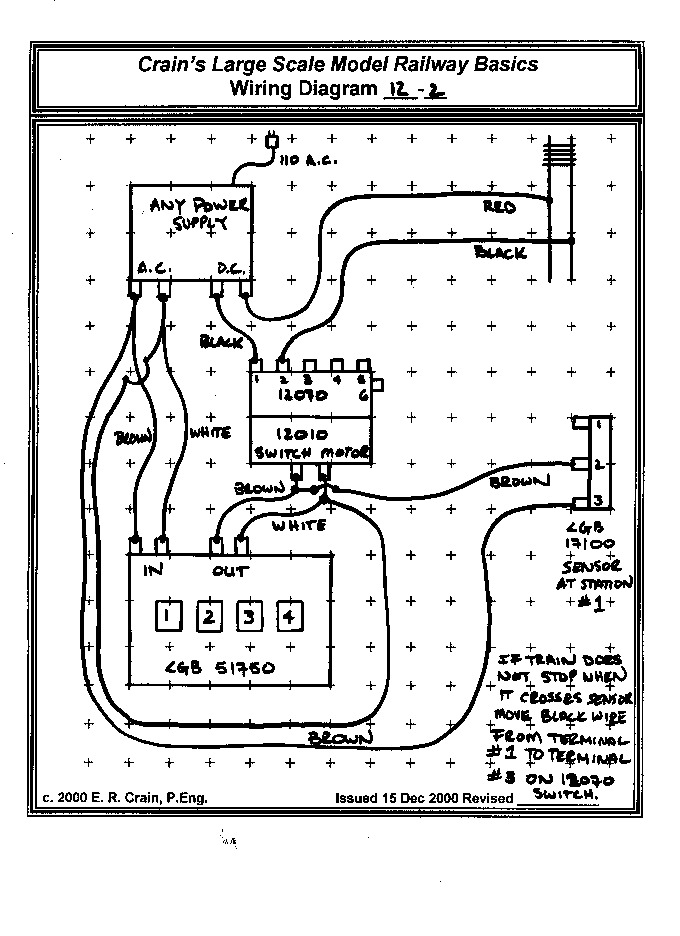
don’t mind sudden starts and stops, you can use a 17100
train sensor with one 12010 switch drive and a 12070 auxiliary
switch to stop the train. You will have to press a button to re-start
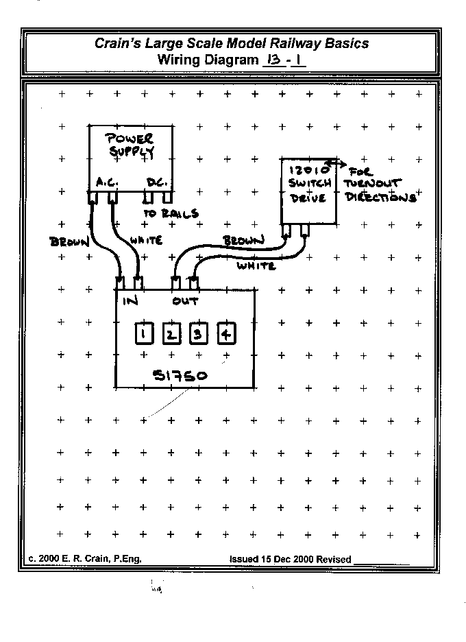
the train. See Page 13 for details on wiring the switch drive. You will need an LGB 51750 momentary contact control box, an LGB turnout with 12010 switch drive attached, and AC power from the AC output terminals of a power supply (eg. LGB 50111). The 12010 should be attached on the “straight through” side of the turnout. If you must place it on the curved side, you may need to shorten some ties to prevent binding, especially if a 12070 auxiliary switch is plugged in.
Connect
the two AC terminals of your power supply to the input terminals
of the 51750. Run a pair of wires from the first set of output
terminals on the 51750 to the 12010 switch drive. There are four
screw connections on the 51750 for each of the four switches.
You need only the orange and white ones - ignore the green and
yellow pair. Use your colour coded wire (white/brown or white/orange)
and connect the white wire to the white terminal on both the 51750
control box and the 12010 switch drive. Connect the coloured wire
to the orange terminal on each device. ALWAYS turn off or pull
the plug on a power supply before connecting wires.
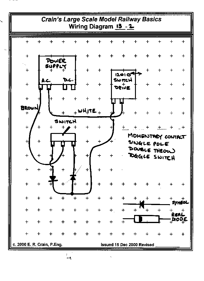
You
can use a Radio Shack momentary contact, single pole, double throw,
center off toggle switch (with two diodes) to replace one switch
on the 51750 control box. This is handy when you want to put switches
on a control panel. Connect the white wire directly between the
AC power supply and the switch drive. Connect the coloured wire
to the center terminal of the SPDT toggle switch. Connect one
diode to each of the end terminals. The line painted on the diode
should face toward the switch on one terminal and away from the
switch on the other terminal. Connect the free ends of the diodes
together and attach a coloured wire to this point. Run this wire
to the switch machine. Diodes should be rated at 1 amp 100 volts
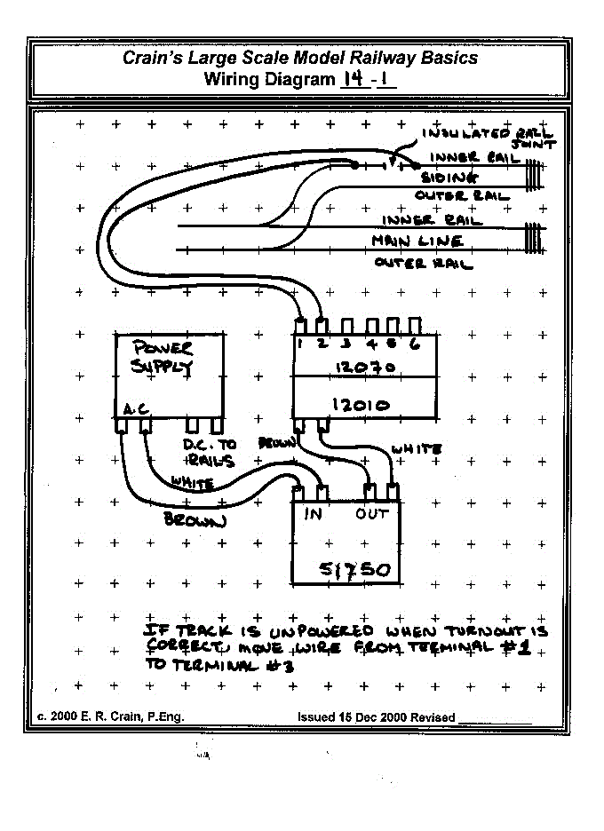
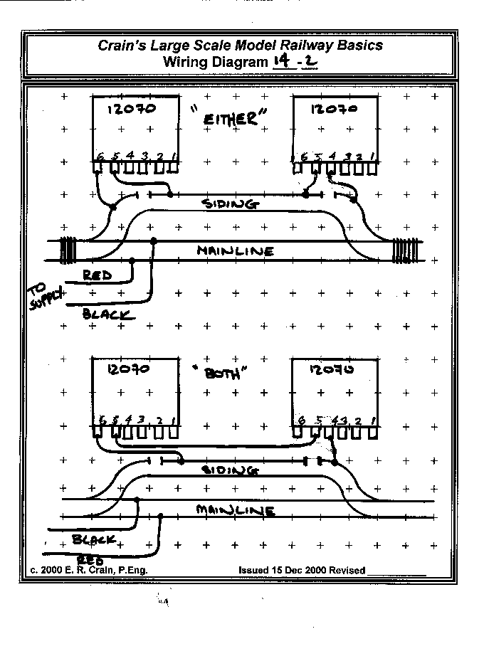
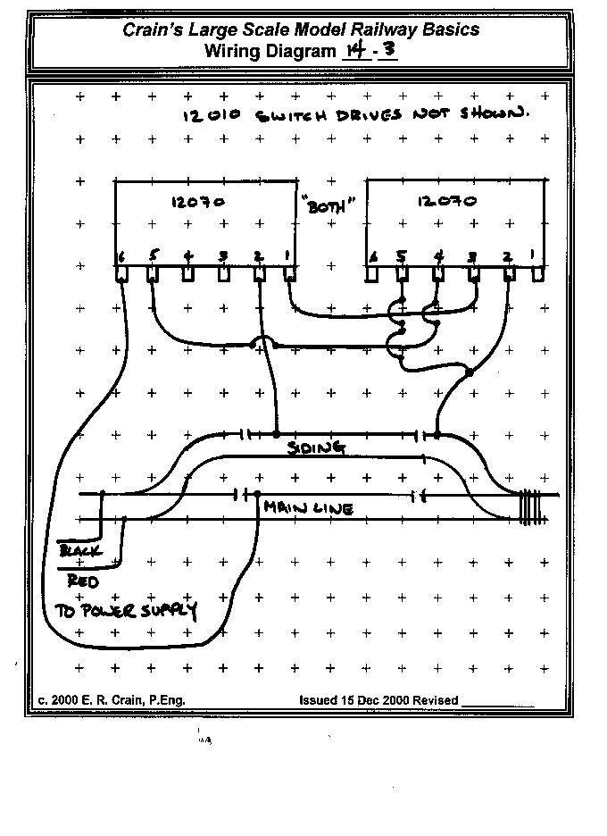
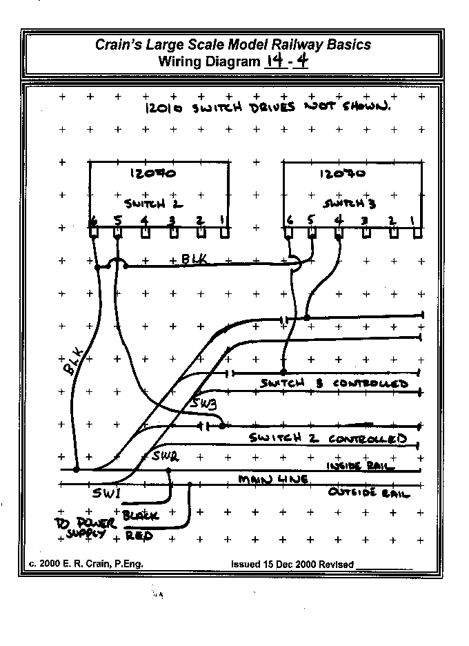
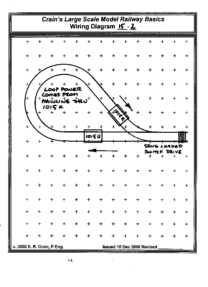
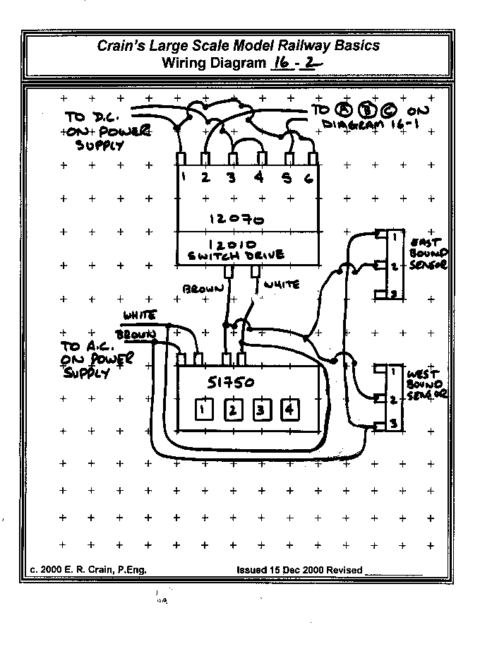
or higher. You can also shut off power on each track, using LGB 12070 switch units attached to each switch machine, as described in Page 14 below.
Pull the metal track joiner off the “inside” rail of the first piece of track (after the turnout) on your siding. The inside rail is the one that is furthest away from you when looking into the railway from the outside. Put a plastic insulator on that rail and connect the track sections. Now the siding is isolated from the mainline and no locomotive can run on it because no power can get to it. You can also use LGB 10153 (1015U) insulated track sections in place of the plastic rail joiner.
To
get power to the isolated rail, add an LGB 12070 auxiliary switch
to the 12010 switch drive on the turnout. Run a black (or blue)
wire from the inside rail on the mainline to a terminal #2 on
the auxiliary switch. Connect another black (or blue) wire from
terminal #1 to the isolated rail. Now the track should be powered
when the turnout aims at the siding and not powered when the turnout
is set for the mainline. If the siding remains unpowered, remove
the wire from terminal #1 and connect it to terminal #3.
The
wiring technique described here is called “common rail”
wiring. The outside rail is the common rail, as there are no insulating
track joiners on this rail anywhere. The isolated rails are always
the inside rail. This keeps the wiring and the thought process
as simple as possible.
Step
1. Isolate and Power the Reverse Loop Tracks.
1. Using Conventional Power Supply. View full size Wiring Diagram 15-3.
Step
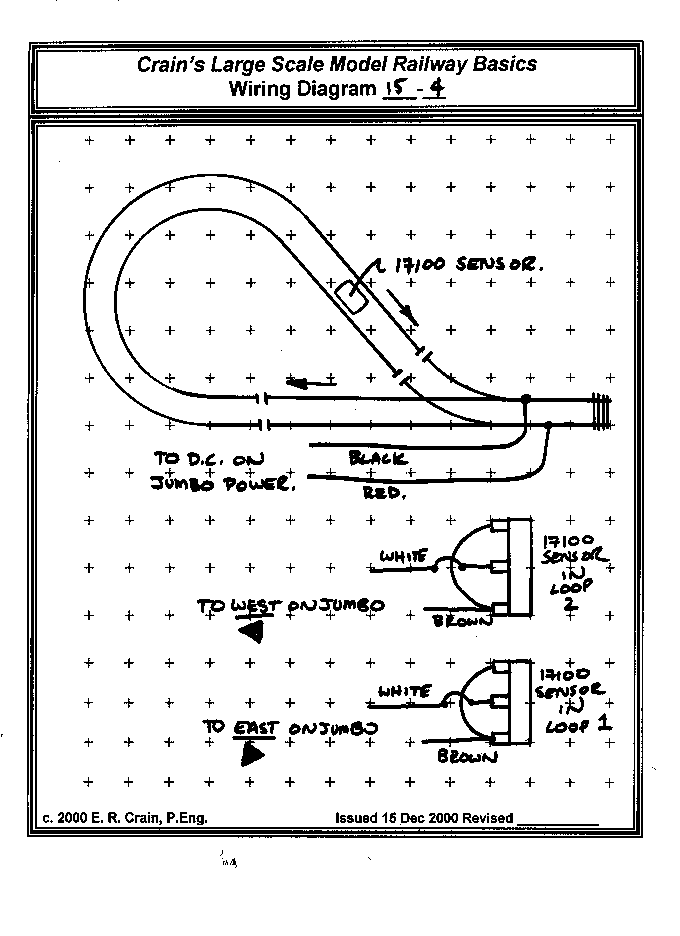
4. Test the Track Polarity. Turn on the track power to a halfway position. Swipe the train sensor in one loop with a 17010 switching magnet. Place one lead of the test light on the outside rail of the loop track. Place the other lead on the inside rail of the mainline. If the bulb lights up, the polarity is correct. If it does not light up, reverse the polarity of the mainline track wires at the power supply terminals. Test the other loop after swiping the track sensor inside that loop. It may be necessary to swap the sensor leads to either the 12010 or the Jumbo to force the correct polarity.
Step
5. Make the Turnouts Turn.
2. Motorized Switch Drives
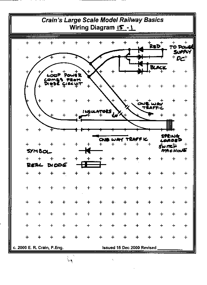
Connect
the inside rail of the siding to the inside rail of the mainline
(not to the isolated portion of the mainline) through a diode.
Similarly, connect the isolated portion of the mainline to the
mainline through a second diode. The painted indicator line on
the diodes will face in opposite directions. These diodes must
be rated at 100 volts and 5 amps or better, because they will
carry the same amp load as the total train. Install LGB 12000 spring loaded switch drives to both turnouts. Set the spring loaded switch drives to aim the tracks into the siding at one end and into the mainline at the other end. The sidings are now “one-way streets” because of the diodes and the spring driven turnouts. When one train is West bound, the other cannot travel. As the West bound train enters it’s siding, it will slow down gracefully, stop, and reverse the track polarity. This will slowly start up the East bound train and the cycle will begin again. You can install station stops elsewhere along the mainline as on Page 12. Test the sidings with your light bulb to confirm that the diodes are facing the right way, and swap them if they are wrong.
There are three critical dimensions to ensure compatibility with other modules: 1. length of 47 3/16" (1.2 meters or 1200 millimeters) to match the length of LGB track. 2. table top height of 40" from floor to top of plywood - clubs may choose a lower height to appeal to a younger audience and have an alternate set of longer legs for compatibility with other clubs. 3. center line of the outer track is 4" from the front and inner track is 11 3/8" from the front.
The
ends of the track meet exactly at the edge of the module for connection
to the next one. The table frame is made of 1x4 lumber and covered
with 3/8" plywood. Legs are hinged and attached to a support
board under the table so they fold up into the frame. The legs
have adjustable screw type feet to correct for uneven floors.
A C-clamp is used on each end to hold one module to the next.
Cormer Top Front End Underneath Wiring These drawings were created by Rick Henderson, Mystic Springs Railway, and were downloaded from Large Scale Online. The standard depth of a module from front to back is 30". Some build deeper modules to allow additional space for structures and scenery. As long as the front edge and tracks line up correctly, the depth is not a problem. You could even have a section drop down for a bridge or trestle as long as the ends remain at the correct height to connect to the adjacent modules. Extended scenes, sidings, and yards can span several modules.
Wiring connectors between modules are 4 wire plug and socket sets used for wiring holiday trailers, found in automotive supply stores. Connectors are mounted on the rear edge of each module and extend 6" beyond the ends of the module. A second set of wires may be used to carry auxiliary power for accessories. Corner modules are used to connect the straight modules into a loop. Corner modules are fairly large and may not be handy to transport. They are often built and owned by the club. Some individuals construct their own so they may have a complete operational layout at home. Two corners together give a 180 degree turn and a center opening of 5' 6" inside the display if all the straight sections are 30" deep. The center opening is for the operators who can get to any module in case of a problem during a show. Painted backdrops are not required but look good if all modules have a uniform style. Club members need to choose an era and locale for their scenery to make an attractive display. Otherwise the sky is the limit! If you are not interested in compatibility with other clubs, you can choose your own dimensions and materials. I built 4 modules with styrofoam (2 inches thick) to my modified “Del Oro” standard dimensions. I added a mahogany facia board, a 2 by 4 foot backdrop (2 inch styrofoam), and scenery as described elsewhere in this website.
My
objective with my model railway is to create a realistic-looking
large scale narrow gauge model railroad without strict adherence
to a particular prototype or era, while allowing for a bit of
whimsy and "time-sliding". After all, it's my railway
and I'm the President and Chief Engineer. I can run it any way
I want! Establish two or three major scenic elements - a station, an industry, or a town. Choose rolling stock and buildings that mirror your ground rules. If gardening is part of the plan, allow for growth of the plants. Keep garden maintenance chores in mind. Plan your drainage very carefully and integrate scenic features such as bridges and trestles into this plan. Lots of mini-scenes, some good sound effects, some lighting for evening operations, good scene separation by trees, mountains, or buildings, and some elevation changes help provide the illusion of distance and space. Properly scaled figures, animals, and vehicles make the scenes come alive. Avoid mixing different scales or eras of rolling stock. You can own a variety - just don’t run them all at the same time. You could “update” a railway in minutes by changing vehicles and people to “set the era” and run the appropriate trains for that time period. You could even swap out a few buildings to give appropriate background for a modern train and swap them back again for an old-timer. My Rocky Mountain House, Nordegg & Pacific Railway is semi-scale in many ways and there is quite a bit of leeway in what passes for realism. The fact that the track gauge is a little too wide for the scale or that Moguls are pretending to be Consolidations or that the grab irons are not right doesn't bother me. I love to look at other people's fine-scale models but I can't build them myself, so it’s the illusion of realism that counts with me, not “real” realism. You may decide to have more whimsy, or more fidelity to scale, or more prototypical operations), or more garden and less trains. It’s your choice and you are free to change your mind any time. Whatever illusion you strive for, have fun!
Chicken grit and white glue ballast on my indoor railway represents
high grade limestone gravel
represent a granite or sandstone gravel. I paint the visible side of all rails with Floquil “Rail Brown” before laying the ballast. Some people paint the ties a more weathered grey-brown to eliminate the “fresh creosote” look of commercial track. Clean the top of the rails with paint thinner on a paper towel, then scrub with a dry towel after painting. To ballast the track, mix 1 part white glue with 1 parts water in a large squeeze bottle. Add a good squirt of dish detergent to make “wet” water. Stir well but do not shake. Squeeze the glue mixture out of the bottle between the track ties and beside the ties for a stretch of 4 feet or so. Don’t worry about glue on the ties - it will run off or get wiped off when you spread the ballast. Buy the glue in 1 gallon (4 liter) containers from hardware stores - I have used more than 20 gallons in 10 years on roads, ballast, and grass on my indoor railway and about the same on my outdoor railway. Indoor white glue is cheaper but can only be used indoors. Outdoor glue is needed for the outdoors.. Pour the chicken grit ballast between the ties (between the rails first). Spread and level the grit and tamp gently with a blunt instrument. Ballast should not fill above the ties. Brush all excess ballast from the rails and the tops of the ties. Keep grit out of switch machines, guard rails, frogs, and switch points. Finally, pour more glue on the top of the ballast until it is soaked through. Then pour more ballast outside the rails. Shape the slope outside the ties, tamp gently, then pour the glue on this part of the ballast. Wipe top surface of rails clean with a damp paper towel then scrub thoroughly with a dry paper towel. The glue may run to undesirable areas. Use paper towels to soak up excess. Protect floor and carpets with plastic sheet. Move on to the next four foot section and start over. Repeat the glue mixture at least two more times, spaced 24 or 48 hours apart. The glue dries clear and the ballast returns to its original colour. Indoors, sprinkle brown and black powdered chalk or poster paint sparingly to the ballast to give some colour to the monotonous grey of the chicken grit. Real trains dripped a lot of oil over time, not to mention what comes out of older passenger cars. A one inch dry paint brush is helpful in spreading the loose powder off the ties, while leaving hints of weathering. Add some weeds on branch lines and along the edges of the ballast. Outdoors, I use mahogany stain to create a brownish tinge to the ballast. For mainlines, you might leave the ballast natural grey. Indoor white glue is water soluble so if you want to rip up some track, soak it for a few hours first. Then pry gently. When lifted out, soak the track sections in a large pail and scrub off excess glue and ballast. Outdoor carpenters glue also dries clear, but it is not water soluble, so you cannot recover the track easily. It is, however, pliable like the soles of running shoes and can be peeled from the track, with some effort. It’s a dirty, boring job, but someone has to do it!
Paint full strength white glue inside the road outlines. Pour on a one-eighth inch (3 mm) layer of grit onto the glue. Wait 2 hours. Then fill a squeeze bottle with white glue, diluted with 1 parts water to one part glue. Add a squirt of dish detergent and stir well before applying the glue over the gritty surface. This will seal the road surface. While wet, you can sculpt ruts or potholes. Wait 24 hours and apply a second seal coat. Repeat as needed for thicker grit. Be sure the grit is slightly below track level at rail crossings.
Build a plank road crossing using popsicle sticks (craft sticks at craft stores). Be sure to cut off the rounded ends of the sticks. Weather them a bit by scuffing with a razor saw or hack saw blade. Paint light grey or tan. Fasten the crossing to the track ties with full strength white glue. Use the same technique to build board side walks and steps. When the road is really dry, a thin wash of brown or grey paint may be desirable on the gravel. I used the same acrylic spray paints as I used earlier on the styrofoam - a very light overspray of several shades looks best. Powdered chalk or a dusting of dry poster paint sealed with a light spray of Krylon matte finish also works well. Good quality art board painted light to medium matte grey makes an attractive paved road. Only brand new pavement is black. Score minor cracks with an Xacto knife. Patches made with tar can be drawn with fine black felt tip pens. Apply white or yellow lines with thin drafting tape. Minimum pavement width should be 8 inches. A coat of Krylon matte finish will seal your artwork and allow you to wipe off dust and dirt once a year.
Shoulders
on paved country roads can be the same grit as described for the
gravel road. In urban areas, concrete sidewalks may be needed.
Build up the sidewalk with art board to 3/16 inches above the
road surface. Test fit the pieces then paint with Floquil “Old
Concrete” and draw or score the expansion lines. To install
roads and sidewalks, use white glue and weight the art board while
the glue dries. This is your chance to become a qualified civil engineer!
Rugged styrofoam scenery is dotted with weeds, grass,
Outdoors,
I use indoor/outdoor carpet (astroturf) as a starting point. It
is laid on a two inch layer of redwood bark which sits on the
soil underneath. This allows the carpet to drain and dry
properly and the bark prevents mold. Where trees, roads, or
buildings coincide with greenery, I place everything on
green-treated plywood, with lots of outdoor white glue. The
carpet extends as far as necessary to reach the rocks or track
ballast, so that it bleeds into the permanent scenery. In turn,
all this sits on the redwood bark. Weeds between the rails or in the ditches can be made from small tufts of ground foam spotted in individual drops of white glue. Shag carpet tufts and knitting wool are also used. Some decorative dried flower leaves look like broad leaf weeds. Wild flowers come from tiny dried flowers found in the craft stores. Spanish moss, also available at craft stores, hobby shops, and my back yard, can represent wild bushy areas. Mice got into my train shed this year and harvested much of my natural scenery materials –they’ll get mouse bait next year. I’ve also had to apply ant bait in a few locations from time to time. Grass and weeds grow everywhere, except maybe on mine tailings, paved roads, and deserts. Spread greenery liberally just as nature intended.
Small
cuttings from these trees form bushes and shrubs. Each tree is
doctored or cut to individual shapes - too many identical trees
won-t look right. Some Christmas decorations are too conical.
These are hard to fix and I still have a few that need to be replaced.
Most trees have a wire mandrel in a base so they will stand up on their own. Pull off the base. Drill a hole in the plywood or poke a slim hole in the styrofoam for the tree. More white glue and plant the tree. Tree size and spacing should be quite random, but there is no point hiding small trees behind big ones - we don’t have to be that realistic. Most should stand vertically, but near dead on wind blown slopes could lean a bit. Gather some small branches from the nearest neighbour’s hedge and use these for deadfall under the live trees. Several detail parts suppliers sell tree stump castings to use in a cut-over woodlot. Pola and others have axes, bucksaws, Swede saws, logging tools, and wood piles to add to the forest scene. Some deer, moose, and birds, a hunter, a hobo, a moonshine still, or a family picnic could improve your forest immensely. A recent Model Railroader article was titled “Trees Are Models Too”. If you have the time, you can model trees to very realistic standards. So far, I have not tried this - I guess it depends on your personal priorities.
1. For lakes, use a flat piece of styrofoam surrounded by higher
sculpted landscape. Paint the lake very dark blue-green or black
with lighter blue to brown around the edges. Cover this with three
coats of clear varnish. Decorate the shore with real sand, fine
dirt, weeds, logs, a dock, some trees, a moose, a fisherman and
you are done. Don’t forget the white glue to hold everything
down. 3. For water falls, make several small pools as above at various elevations, then connect the higher pool to the next one down with silicone caulk. The silicone can be spread on white styrene first and then cut to length. Touch up the silicone where it leaves the upper pool and where it joins the lower pool. Paint some white water on the silicone and where the water hits the lower pool. Use some white glass wool to represent foam. Lots of rocks and white water make the scene. Vegetation abounds around the spray. There are several low melting point plastics on the hobby market that can be used to replace the varnish. The plastic runs like water, so it is still difficult to get any depth to the scene. You can’t see into most water in North America anyway, so this is no great loss. However, you can tease this stuff into waves as it cools and a little paint can create white caps. CAUTION: the low MP plastics can melt Styrofoam. I have two other water features. One is a large blue carpet with white fleck on the floor to represent ocean in front of Gorgeous Gorge. This photographs beautifully. Gorgeous Gorge is a four foot water fall, but not built exactly as described above. It is carved from the styrofoam, painted, and decorated as for the meandering stream. The reason for this is that most of the waterfall is hidden by three bridges and lives in shadow most of the time - no fancy details needed. A few beaver, some bears, and a troll inhabit the dimness.
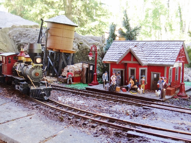
A primary scenic element is the railway station with all the details
of passengers, baggage, and freight. Add water tank, coal or
oil and sand facilities, yard crew, and vehicles appropriate to
the era and the scene is grand - maybe too grand. The eye sees
it all but concentrates on nothing. Now add distinctive elements
to the scene - a lady kissing her beau goodbye, a porter capturing
an escaped goose, a trainman oiling a journal box, a dog with
a squirrel up a tree. Each is a separate memorable mini-scene
set on the visual stage of the train depot. There are many mini-scenes on my railway to draw the eye to specific places on the layout. Mini-scenes include a Christmas party in a remote corner of the railway, a young lady kissing her beau goodbye at the station, another young lady photographing a mama bear and cub, beavers chewing a bridge support, a hunter aiming at distant deer, ladies of the night eating ice cream on the hotel porch, linemen stringing new telegraph wire, diners at an outdoor restaurant, geese escaping from a cage on a baggage cart, Marilyn Monroe and Clark Gable being greeted by the mayor, the wedding party photographer, a school band practicing, firemen washing the fire truck, a biker gang partying and holding up traffic, a wingwalker on a biplane, a traffic accident with nurse and ambulance, . . . . . You can think of hundreds more to bring life to the static scenery. Building interiors are also good places for mini-scenes. Since they are not as easy to see, they can be less detailed, but just as interesting. Adequate furniture, floor covering, wall and partition covering, a human or two, some details such as books and dishes make a house a home. Stations and industrial interiors need good walls and floors, appropriate furniture or machinery, baggage or parts, and people working at their jobs. If a portion of the roof is removable, you can show off the detailing to visitors or add to it as time permits. Most commercial building kits are highly compressed versions of the real thing, so you will have to compromise on some features, such as omitting closets and entry halls in houses, or leaving out the staircase to the upper floor of a hotel. Don’t fret - no one will notice except you!
Some passenger cars and cabooses come with lighted interiors and/or marker lights. Some are equipped with constant voltage circuits. Others are battery powered, giving constant lighting intensity until the batteries die. In daylight, these cars should have their lights turned off, so a switch should be mounted under each car for this purpose. If no switch exists, any Radio Shack mini-toggle switch will do. Drill a hole in the floor of the car to accommodate the switch. Cut one of the wires leading from the track pickup brushes, or battery box, to the lights and solder the cut ends to the switch. If the car is lighted by batteries, you may get tired of replacing batteries, and wish to put in a track powered constant intensity lighting system. You may also wish to light up your unlighted rolling stock. Several components are needed for each car to be lighted: 1. one 5 volt DC regulator with 24 volt (max) DC input, 0.50 amp output (min) Watts Trainshop 5VCB or equivalent 2. several 5 volt clear light bulbs (each bulb draws 0.25 to 0.55 amps) LGB 68511 or equivalent 3. track power pickup brushes LGB 63120 or equivalent 4. brush holder to mount brushes to passenger car trucks LGB 63193 or equivalent 5. metal wheels and axles for the trucks (any brand will do) 6. rear end marker lights for last car on train or cabooses LGB 68332 7. miniature on/off toggle switch Radio Shack or equivalent LGB passenger cars have the brush holder built into the trucks, as do the newer 4 wheel cabooses. You can also skip the 5 volt regulator and use 18 - 24 volt bulbs instead. This costs less but you lose the constant intensity lighting effect. Track power pickup brushes act like brakes on the wheelsets and the train will be much harder to pull. Ball bearing metal wheelsets reduce this problem. Here’s what to do. Wiring Diagram 42-1. 1. Remove the trucks from the passenger car. Install the brushes and brush holder on one or both trucks. Solder a wire to the outer housing of each brush. Install the metal wheels in the trucks. Use masking tape to hold the brushes in their retracted mode while installing the wheel sets. Remove the tape. 2. Remove the roof from the car. Drill a hole in the floor for the toggle switch and mount it. Drill another hole and feed the wires from the brushes into the car interior. Re-mount the trucks. 3. Solder wires to the light bulbs and solder these wires to the 5 volt regulator’s output terminals. Build a mounting strip to hold the bulbs and the regulator. Fasten this to the roof of the car with double sided tape. Remember that the bulbs get hot so they should not be allowed to touch plastic or metal. 4. Connect the wires from the brushes to the input of the regulator, connecting one of these wires through the toggle switch on the way. If you have brushes on both trucks, be sure both wires from the righthand side of the car are connected to each other - ditto the left side. 5. If marker lights are going to be installed, drill holes in side of car (if needed). Feed wires through holes from marker light bulbs to the regulator. Install marker light housings and push bulb into interior of housing. LGB markers come with 24 volt bulbs and sockets, so you must replace them with 5 volt bulbs if you use a 5 volt regulator. 6. Double check all connections, looking for bad solder joints or bare wires that could touch each other. Bundle wires neatly above the tops of the windows and re-install roof of car. 7. Flip the toggle switch to the “on” position. Test the car on a test track connected to the DC terminals of a good quality power supply. If circuit breaker clicks off, you aren’t finished. Check all wiring, especially around the brushes – don’t let bare wires touch wheels or axles. That’s all folks!
Outdoor wiring must be weather-proof and connections must be made in a safe manner, such that water cannot enter the connection and cause a short circuit. Some garden railroaders run conduit with weatherproof junction boxes. Others run wires beside the tracks and hide them with ballast, with the connections made inside the buildings. Light bulbs must be protected from the weather - a drop of cold water may crack a hot bulb. Most people do not turn on outdoor building lights when it is raining, just to be safe. If only interior building lights are needed outdoors, good quality outdoor Christmas tree lights could be used. These are pretty weather resistant and can withstand some abuse. Keep the bulbs away from walls and ceilings of the buildings - they will melt plastic or char wood if too close. They should be plugged into a ground fault protected outlet. On my indoor railway, I use LGB 68502 18 to 24 volt screw base bulb and socket sets, but any brand of 18 to 24 volt lamps will do. Install lamps in buildings that would normally be lit at night; some stores might not be open after 6 pm! Many buildings will need lights over the entry doors. Commercial products are available for this purpose, or you can fashion lamp shades for LGB bulbs from cosmetic bottle caps. If building interiors are finished as mini-scenes, lamps and lamp shades might have to be more finely detailed. Commercial street lights and lighted advertising signs are also attractive additions. Choose models that fit the era you are trying to represent. I find many so-called G Scale streetlights too tall to be visually pleasing. I have cut 2 or 3 inches off the base of some. I have also found some O Scale gooseneck street lamps that look great. Unfortunately, the really cheap Christmas village street lights are too short, but could be lengthened with some brass or plastic tubing. Run wires from each building or street light to one of your distribution boxes (junction block or connector block). Mount a heavy-duty, automotive-quality toggle switch somewhere handy. Run one pair of wires from each junction box to the toggle switch and from there to your AC transformer. You might want to use more than one toggle switch to control different elements of your lighting projects. Double check all connections - make sure there are no bare wires showing anywhere and that all bulbs are protected from the weather. Plug in the transformer and flip the toggle switch to the “on” position.
Outdoors, you should consider walkway lighting, so visitors can wander safely without wrecking your scenery. Some overall lighting to aid visibility is also a good idea, but every setting will require a unique solution. Be a good neighbour and keep light pollution under control.
I
saw a neat idea on one railway - it used fluorescent ink to mimic
neon signs on some buildings. They glow brilliant colours when
flooded with “black light” (an ultraviolet fluorescent
light bulb - the kind that makes the bleach in your white shirt
glow at the local country dance).
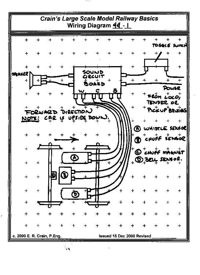
To install the aftermarket sound system, some minor butchery will be needed. First, read the installation instructions for the sound unit, and identify the components. Then remove the coal or wood load from the tender, or remove the body from the loco, or remove the roof from the boxcar. Test fit the speaker to see where it can best be located. The instructions will give some suggestions. When the best spot is chosen, drill some holes to let the sound from the speaker get out. More holes equals better sound. Mount the speaker with double sided foam tape or self tapping sheet metal screws - drill pilot holes first. Now find space for the circuit board. It is often stuck to the roof or coal load with double sided tape. Test fit the car or loco back together to check for interference between the speaker and the circuit board. Continue by gluing the sensors for whistle and bell to the truck frame so that they are in-board of the wheels and no more than one-eighth inch (3 mm) above the rails. To be compatible with existing LGB sound locomotives, the whistle sensor is on the right side of the car or loco when it is facing forward. For steam locos, glue the “chuff” magnet to one axle on the truck and glue the chuff sensor so it is 3 mm from the magnet on the axle. Cyano-acrylic (CA or crazy glue) is used to glue these components to the truck frame and axle. Some spacers may be needed – styrene or wood is fine. Paint the spacers and sensors black to help hide them from view.
When
the glue is really dry (15 minutes to an hour), feed all the sensor
wires through the floor. Solder all wires inside the body to their
correct terminals, following the installation instructions. If the sound system is in a locomotive, identify the wires that pick up power from the wheels and connect the sound system power leads to these two wires. For tender installations where track power is available, hook up the sound system power to these two wires. For boxcars or tenders with no power leads, more work is needed. First, you will need a metal wheel set for at least one axle of the truck that does not have the sensors glued to it. I recommend metal wheel sets on all axles to guarantee that all wheels are the same size. Then install LGB electrical pickup brushes (LGB 63120) into the mounting slots on the truck (assumes you are working with LGB tender trucks with molded in slots for brushes). Solder wires to each brush holder and feed the wires through the floor and connect to the sound system. For non-LGB trucks, install LGB 63193 brush holder with LGB 63120 brushes. The bell and whistle sensors are activated by magnets placed between the rails. LGB 17050 or generic magnets from Radio Shack work fine. The whistle is activated when the magnet is beside the right hand rail, the bell by a magnet beside the left hand rail (in-board of the rails). LGB magnets snap in place between the ties. Generic magnets should be glued down so they won’t grab and stick to the first metal object to pass by. Check hobby shop websites or ads in model magazines for manufacturers and prices - competition is fierce in this area right now. Manufacturers such as Sierra Sound, Phoenix Sound, SoundTrax, and others are the main suppliers.
Make It Real With Ambient Sounds
I recorded one tape with wildlife sounds – crickets chirping, birds singing, frogs croaking, wolves howling, gulls screeching, loons calling their mates. This plays to two separate speakers near my water features. The other side of this tape plays wind, rain, thunder, and gurgling water. Alternating these two effects reduces boredom. Volume is set low enough not to intrude. These sounds were recorded from Solitudes CD’s. Many such relaxation tapes and CD’s are available at record stores or novelty shops. Choose the portions without music and fade the sound in at the beginning of each segment, and fade them out before the end to eliminate clicks. Another tape consists of distant train sounds - whistles, steam chuff, clanks, and clickety-clack - to represent trains in the distance, unseen but present in the 3-D space of the model. This also plays at a non-intrusive level to two speakers set low to the floor, so that direction is confused. A second version of this tape with similar sounds, but in a different order, plays to two more speakers. Even when my sound equipped trains are parked, I can “see” the entire railway with my ears. I am legally blind, so I see a lot of things this way. Train sounds are harder to find, especially sounds that are reasonably correct for the era and road you are modeling. I used sounds from two CD-ROMs by Sandia Software and a couple of tapes and a 45 RPM record found in a second hand store. Videos of train run-bys may also provide good recorded sound if there is no voice-over or music to ruin it. Cattle and sheep sound modules are easily put into cattle cars or farm yards. LGB sells some cars with these sounds built-in. Chicken, pigs, and other chips are available for farm yard use. Check hobby shop websites or ads in model magazines for manufacturers and prices. Keep the volume down and localized. You may need to invent a method to run the sound chip sporadically rather than continuously - roosters that crow too often usually end up in the stew pot! There are other interesting possibilities that I would like to try. I saw one layout that had bar room piano and chatter - only when you opened the door to the saloon - neat trick. A recent article suggested using cheap 10 to 30 second sound chips to record train arrival and departure announcements. A train sensor of some kind could activate these. Some diesel sound systems have built-in “train chatter”. Church bells, town clock, telegraph clack, auto horns, and the murmur of waiting passengers - any short sequence you can think of is possible.
Try
Me !
|
||||||||||||||||||||||||||||||||||||||||||||||||||||||||||||||||||||||||||||||||||||||||||||||||||||||||||||||||||||||||||||||||||||||||||||||||||||||||||||
|
Copyright © 2022 E. R. (Ross) Crain, P.Eng. email |



 Large Scale trains were first introduced by Marklin of Germany
during the early 1900's. Layouts were set up either in the garden
or the attic because of its large size. These scales disappeared
during the Second World War and post war attention was turned
to the smaller HO and N scale trains.
  By
the mid 1980’s, G scale was firmly established, and several
manufacturers were offering a broad range of rolling stock and
locomotive products for sale (though scale ratios vary between
1:20.3 to 1:32, depending upon manufacturer). Other companies
began to produce accessories, such as buildings, people, and other
trackside items, to complement the layouts being built by G scale
enthusiasts.
 There is more to Large Scale model railroading than meets the
eye. There are SEVEN different large scales, each with its own
name, living under the generic umbrella of “Large Scale”.
Some modelers don’t worry too much about the scale of their
trains - as long as they are “Large”. Many modelers
do notice, and try not to run trains with equipment from different
scales, just as HO modelers would be careful not to run an Sn3
scale boxcar in their fleet, even though it is roughly the right
size.
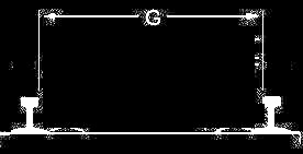 Confusion
is also rampant because most models from the different Large Scales
run on the SAME track gauge. Gauge is the distance between the
inside faces of the rail heads. The usual gauge for real trains
in North America is 4 feet 8-1/2 inches (standard gauge). Many
other gauges have been used, such as 2 feet, 3 feet, and meter
gauge - usually referred to as narrow gauge tracks.

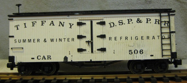
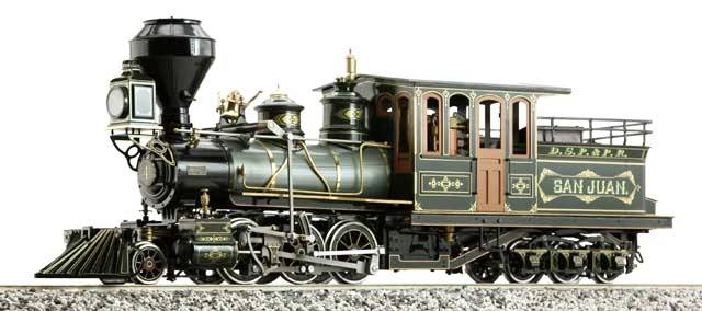
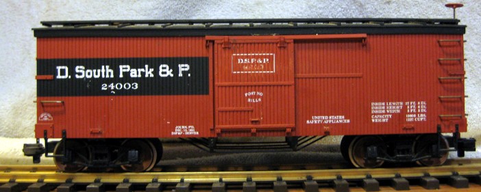 Aristocraft was the originator of 1:29 scale, hence the name A scale for this
size. Most Aristo models are modern era 40 and 50 foot standard
gauge equipment. Some are painted for narrow gauge lines where
appropriate. Aristo also manufactured the Delton Classics line,
which represents 3 foot narrow gauge in F, G, or H scales. Aristocraft closed its doors in Dec 2014 but there is lots for
sale in the aftermarket (eBay).
 There are many ways to learn about Large Scale model railroading.
Books, magazines, videos, and internet sites offer more information
than a single human can absorb. Here are the best sources of information
I have found. Use your favourite search engine using the names
given below -- the links change more often than I care to keep
up with.
 1. Analog power supply with tethered walk-around control.

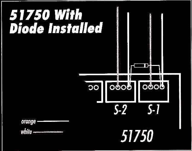 The
diode shown at right must be oriented with the correct polarity
as shown. It should be rated at 100 volts, 1 amp or better.


 Part of making a railway believable is the creation of a reasonable
imitation of recognizable scenic features such as roads, grass,
trees, and water. Indoors, we have to simulate living things the
best we can. Outdoors, we can combine the real thing with some
artistic fakery.
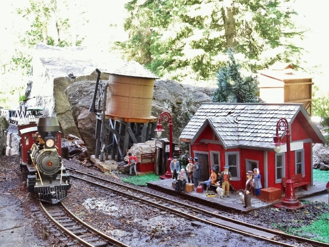
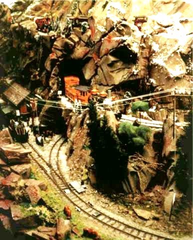 Begin the scenery effect by building roads and ballasting the
track. Forindoor railways, lets assume the plywood and styrofoam terrain is painted
in reasonable rock and dirt textures. Lets also assume most of
the buildings are in place and have been fitted to the terrain
- there is no more glaring error than an unsupported corner on
a building or a bridge.
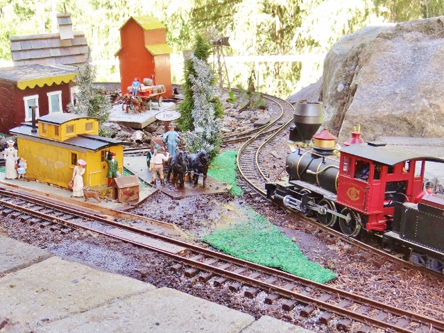
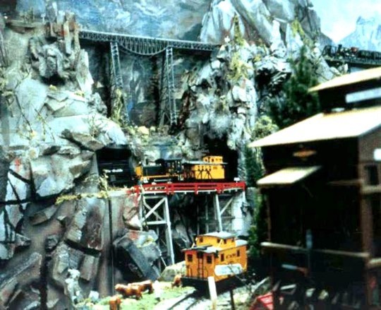 Indoors, I use either the carpet trick or loose ground cover
glued to the underlying plywood or styrofoam. Several
manufacturers offer grass,
weed, and foliage products.
 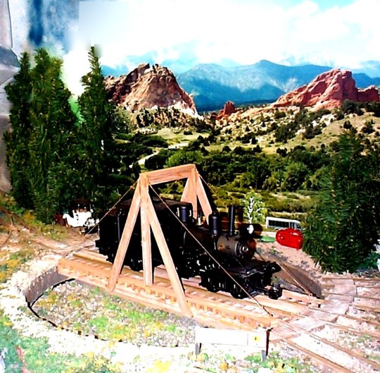 Before you plant trees, be sure your trackwork,
roads, and ground cover are finished in the area. Trees are big
and get in the way. Most of my trees are of three types:
Christmas decorations with no snow for summer scenes, Christmas
decorations with snow for Alpine elevations, and bare fir,
birch, and unidentified deciduous trees at high elevations .This
works for both indoors and outdoor railways and is the cheapest stuff you can buy
at craft stores, especially a day or two after Christmas.
 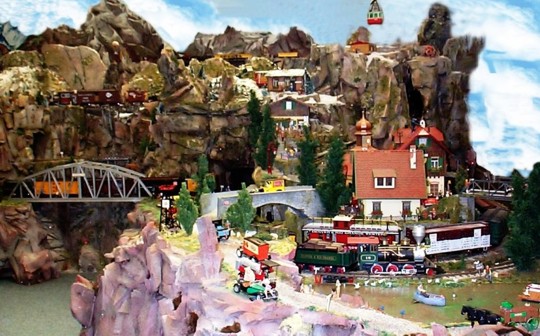 Water features on an
indoor large scale railway are tricky. Outdoors, of course, we
use the real thing. Real
water is almost out of the question indoors, but I’m sure it has
been done. Several good articles have appeared in recent Model
Railroader magazines and the topic is covered well in most scenery
manuals from the hobby shops. I have three suggestions.
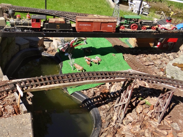
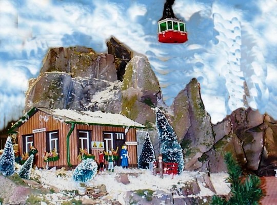 Indoors
or out, mini-scenes are a way of breaking a model railway into smaller,
visually attractive sections. Much of the illusion of realism
of a model railway is lost if the whole railway can be seen at
once. Visual barriers are the cure. These can be groves of scale
sized trees (real or fake), mountains, buildings, water features,
or elevation changes. Within each visual segment of the model,
one or more mini-scenes can be constructed to draw the eye to
the center of the area.
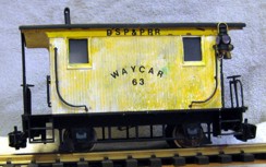 Lighting on a large scale railway doesn’t do much for me
during daylight hours, but at dusk – WOW, I’m a fan!
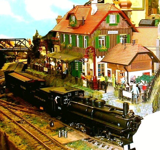 Lighting your buildings and streets is a lot easier than lighting
a passenger car. You need a good 18 volt AC transformer capable
of delivering at least 2 amps. If you can afford it, use a separate
transformer from your train controller - it doesn’t take
long for your lighting projects to load up the current draw. Do
not hook up more than one transformer to the same set of lights.
If your railway is outdoors, the transformer must be kept indoors,
or in a dry, water-proof enclosure. Outdoors, it must be plugged
into a ground fault protected outlet.
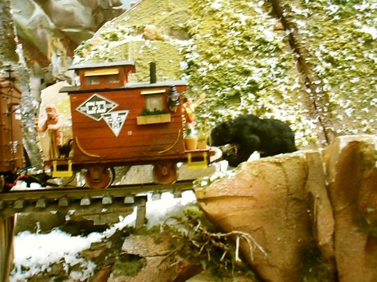 You
may also want to consider ambient lighting. Indoors, overall fluorescent
lighting is needed to cover the whole railway. Some small flood
lights or pot lights on dimmer switches allow you to highlight
sunny areas or change the ambiance from noon to dusk. If buildings
and trains are well lighted, you can even consider running in
the dark, with only a single blue spot for a moon glow effect.


 Ambient sounds add another element of realism. I use several tape
players with different background recordings to enhance the illusion
of space around the railway. You can use this concept indoors
or out - as long as you respect your neighbours, and protect the
speakers from the elements.
